Field note 006 · Reservoir design
Size the reservoir by its operating envelope.
The tank label gives container capacity. The grow loop needs a verified working range between safe drainback headspace and the lowest level that still protects the pump, circulation, roots and service interval.
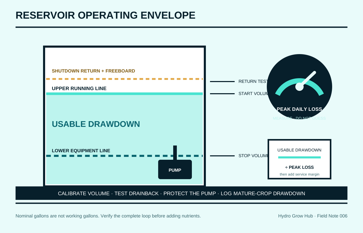
“How many gallons per plant?” is a useful search because an undersized reservoir can expose a pump, concentrate measurement changes and demand frequent attention. It is also an incomplete design question. A 20-gallon container may hold less during operation, a recirculating loop may send several gallons back when power stops, and a mature crop can use water much faster than seedlings.
Virginia Cooperative Extension offers a broad starting range of one-quarter to one gallon of reservoir capacity per plant for small nutrient-film-technique systems and notes that extra volume can buffer pH and nutrient changes. Recent Kansas State University work reviewing leafy-green systems found no standardized optimal nutrient-solution volume per plant and noted that common rules were not based on refereed literature. Those facts belong together: use plant-count guidance to start a comparison, then verify the actual loop.
A useful reservoir specification has five volumes, not one: nominal container capacity, the upper running level, the highest shutdown return level, the lower equipment limit and the drawdown available between normal checks. Add the system’s location, loaded weight, access, opacity, drainage and cleaning path. The result is an operating envelope that can be tested.
1. Separate container capacity from system volume
The advertised capacity is usually measured close to the brim. It does not establish the level allowed by a lid, bulkhead, overflow, pump cord, return fitting or air gap. It also does not include solution held in channels, buckets, pipes, filters or manifolds while the system runs.
Start with clean water and a calibrated transfer container or inline meter. Add measured increments to the empty reservoir and mark the actual volume at useful depths. Molded graduations can be checked rather than assumed. Then assemble the complete loop and measure how much water leaves the reservoir when pumps and irrigation circuits operate.
The maker’s full-container figure. Useful for transport and comparison, not the operating fill line.
All solution in the reservoir, channels, buckets, tubing, filters and returns during operation.
The measured amount left in the reservoir while every planned circuit operates.
The volume between the upper running line and the verified lower operating line.
Do not estimate a rectangular tote by outside dimensions. Wall taper, rounded corners, molded ribs and unused headspace change volume. A marked calibration scale gives the reservoir log a real volume reference and makes leaks, plant uptake and evaporation easier to distinguish.
2. Mark upper, return and lower lines
The upper running line is the highest level permitted while the full system operates normally. It must leave enough space for solution that returns when the pump stops, including channels, supply lines, elevated buckets and filters that drain by gravity or siphon.
- Assemble the final plumbing. Use the planned channel heights, tubing routes, valves, filters and emitters.
- Add measured clean water. Keep every electrical connection dry and follow pump minimum-level and start-up instructions.
- Operate every circuit. Purge air as instructed and wait until flow and return levels stabilize.
- Mark the upper running line. Record reservoir volume while the loop is stable.
- Shut down safely. Observe the full return and any siphon. Mark the highest shutdown level.
- Keep freeboard. The return level must stay below the lid, overflow, cord opening and electrical zone with a practical margin.
Repeat the shutdown test after cleaning filters and changing valve positions because flow paths can alter drainback. If the return threatens to overflow, lower the running line or redesign the plumbing. An overflow is not an acceptable way to discover total system inventory.
The lower line comes from equipment and crop requirements. A submersible pump may require a minimum depth for cooling and reliable intake. A heater, chiller coil, level sensor, float valve or dissolved-oxygen probe may have its own immersion range. Deep-water-culture roots need a planned water-to-air relationship; NFT systems need enough volume for the pump to keep every channel supplied.
University of Minnesota Extension warns that an NFT reservoir falling below its pump can damage the pump. Use the highest minimum required by any component, then add a service margin rather than letting the intake become the alarm.
3. Size the service interval with measured drawdown
Usable drawdown is the upper running volume minus the lower operating volume. The reservoir should remain above the lower line for the entire interval between reliable checks, at the crop’s highest observed water use and the room’s expected evaporation conditions.
Measure daily change at the same time and operating state. Record starting volume, ending volume, any additions, spill or sample removal, crop stage, room temperature, solution temperature, pH and EC. A falling level can reflect plant uptake and evaporation; a sudden unexplained loss can indicate a leak. Never normalize a leak into the sizing allowance.
| Input | How to obtain it | Use |
|---|---|---|
| Upper running volume | Measured with all circuits stable | Starting line |
| Lower operating volume | Highest equipment or crop minimum plus margin | Stop line |
| Usable drawdown | Upper minus lower | Available service buffer |
| Peak daily loss | Highest verified 24-hour change at mature crop load | Planning rate |
| Check interval | Longest period between dependable inspections | Required buffer duration |
| Shutdown return | Highest measured level after safe pump stop | Required headspace |
For example, if the upper running line is 18 gallons and the verified lower line is 8 gallons, usable drawdown is 10 gallons. If the mature crop’s highest measured loss is 2 gallons per day, the arithmetic gives five days before the lower line. That is not a five-day maintenance promise. Hotter conditions, crop growth, sampling, a stuck float or missed inspection can shorten the interval, so the operating schedule needs a conservative margin and a high/low-level alert when failure consequences justify one.
Do not top off by volume alone. Source water changes pH and EC, and crops do not remove water and every ion at identical rates. University of Minnesota and Oklahoma State Extension both emphasize measuring water quality, pH and EC as water is added. Follow the crop program and fertilizer label rather than automatically replacing every lost gallon with full-strength nutrient solution.
4. Adjust the envelope for system type
Nutrient film technique
NFT keeps a relatively small film moving through channels, so the reservoir, pump, delivery height, friction loss, branch flow and return must function as one loop. Virginia Tech notes that the reservoir sits at the low point and that the pump must deliver the required channel flow at operating head. More gallons cannot rescue an undersized pump, blocked line or poor channel return.
Ebb and flow
The reservoir must supply the full planned flood without exposing the pump, then accept the entire drainback without overflowing. Measure both states at the tray’s maximum fill and with all zones that may run together. A check valve or siphon break can change return behavior; test the actual arrangement rather than using the tray’s nominal volume.
Recirculating drip
Include solution held in media, drain trays and return plumbing. A wet substrate can release water slowly after the pump stops. Collect and time the return through a complete cycle. Uneven emitters and clogged filters are flow faults, not reservoir-capacity problems.
Deep water culture and RDWC
Production vessels are part of the solution volume. Oregon State Extension says DWC uses large volumes that should be supported on the ground, notes that dividing volume among tanks can localize leaks, and recommends opaque coverage to reduce evaporation and algae. Water depth also changes the root air space, so mark the intended production-vessel level as well as the control reservoir.
Passive systems follow a different water-level strategy. University of Minnesota notes that in DWC, a falling level can leave part of the root mass exposed to air as plants develop. A passive system designed to fall through a crop cannot be sized from the refill schedule of an actively controlled reservoir.
5. Verify weight, light exclusion and service access
Water weighs about 8.33 pounds per U.S. gallon, according to the U.S. Geological Survey. A 40-gallon water inventory is therefore about 333 pounds before adding the reservoir, frame, channels, plants, lights, people or concentrated loads from legs and casters. Use a qualified building professional when floor capacity, rental restrictions or structural condition is uncertain. Do not place a large reservoir on furniture or shelving that lacks documented load capacity.
- Level support: keep the reservoir stable and level as its maker requires; twisting can stress walls and bulkheads.
- Secondary containment: plan where the largest credible leak goes, how it is detected and how power is isolated without stepping into water.
- Opaque cover: block light from nutrient solution while preserving ventilation and equipment clearances.
- Service opening: make the pump, float, probes and interior corners reachable without removing the entire crop.
- Drain path: provide a controlled way to empty and capture solution for disposal under local rules.
- Dry electrical zone: route cords with drip loops and keep connections outside the spill and condensation area as equipment instructions require.
EPA explains that storm drains can carry fertilizer nutrients directly to surface water without treatment. Follow local wastewater, solid-waste and Extension guidance for nutrient-solution disposal. “Dilution” is not a universal disposal method.
More volume can slow temperature change, as Oregon State notes for DWC, but it cannot overcome a hot room, direct light, warm pump or poorly insulated location. Record solution temperature with pH, EC and volume. The aeration verification guide explains why oxygen delivery must be tested at the real operating pressure and temperature.
6. Run a seven-stage acceptance test
- Calibrate the volume marks. Confirm upper, return and lower lines with measured water.
- Verify drainback. Stop and restart every pump mode without overflow, siphon surprise or dry intake.
- Leak-test the loop. Inspect bulkheads, valves, filters, manifolds and returns on dry surfaces.
- Measure branch flow. Confirm each channel or emitter receives the intended rate at real head.
- Test the low line. Confirm equipment remains within manufacturer limits before the planned stop point.
- Log drawdown. Track daily volume through crop establishment and the expected peak-use period.
- Practice service. Drain, clean and refill without lifting beyond safe limits or crossing electrical and clean-work zones.
Run clean-water commissioning before nutrient solution. After the first crop begins, use the seven-day reservoir log and extend it through mature demand. Recheck after adding plants, channels, a chiller, different irrigation timing or a new pump.
At crop change, apply the between-crop cleanout. A reservoir that cannot be fully drained, opened, scrubbed and rinsed carries a maintenance cost that nominal gallons do not show.
7. Write the reservoir product brief
Upper running gallons · shutdown return gallons · lower equipment gallons · usable drawdown
Reservoir · channels · buckets · tubing · filters · return volume · simultaneous zones
Crop and count · stage · peak measured daily loss · check interval · alert point
Loaded weight · support · containment · opacity · access · drain · cleaning path
Require exact internal dimensions, material, food-contact documentation, lid openings, bulkhead locations, graduated-volume accuracy, working-temperature limit, pump access, drain geometry, warranty and replacement parts. A “30-gallon reservoir” without a working fill range is not a complete specification.
Hydro Grow Hub keeps branded reservoirs, prices, inventory, availability, sellers and checkout disabled until supplier authorization, verified specifications and accurate commercial terms are documented.
Questions growers ask
How many gallons should I allow per plant?
Use a plant-count rule only as an initial comparison. The final size must accommodate system inventory, shutdown return, pump minimum, crop stage, measured daily drawdown and the real check interval. There is no single research-backed optimum for every recirculating system.
Is a larger reservoir always better?
No. More volume can buffer some changes and extend service time, but it adds weight, cost, cleaning labor and spill consequence. It also does not correct a flow, temperature, nutrient-balance, source-water or meter problem.
How much headspace should I leave?
Measure the full drainback of the assembled loop after a safe shutdown. Keep the highest return below every opening and electrical area with a practical margin. Repeat after plumbing or valve changes.
Can I let the pump intake define the low-water mark?
No. Use the highest minimum specified by the pump and every immersed component, then add margin for the service interval. The pump intake becoming exposed is a failure, not a level sensor.